Research note / Cycle 003
Which part of the strip moved?
A model of a short strip between testing-machine grips shows how a calibration step and a separate grip-motion channel change the meaning of an apparent stretch.
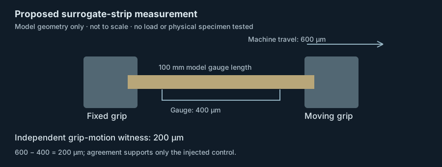
The strip, the grips and the measurement
The Space Elevator Initiative needs a continuous structural ribbon whose defects and deformation can be inspected. A tensile test would hold a short specimen between grips and pull them apart. Crosshead travel measures the machine’s movement; gauge extension measures the distance between marks on the specimen. Neither reading, by itself, says how much a grip moved relative to the strip.
We modelled a 100 mm surrogate gauge length with a third reading for grip motion. This is a displacement model for preparing a bench test. The length does not describe a manufactured tether coupon, and the model includes no force or failure calculation. The preceding displacement note supplied the question; the proposed metrology protocol supplies the channel arrangement.
Give the instrument something whose movement is already specified
Before interpreting the model strip, we supplied a 1,000-micrometre reference step. With a common ten-percent scale error, a true model extension of 400 micrometres reads 440, while 600 micrometres of machine travel reads 660. Their difference is 220. An independent reference reports the scale error: its specified 1,000 reads 1,100. Applying that correction restores the difference to 200 micrometres.
If the supposed reference shares the same wrong scale, both its specified and observed values appear to be 1,100. It approves its own error, leaving the difference at 220. We withhold that case because the reference dependency is unresolved. Two sensors and a reference can still be one calibration mistake.
A visible grip movement changes the explanation
In the known-motion control, the separate grip channel also records 200 micrometres. The readings agree within the authored 55-micrometre combined comparison bound. That makes the difference consistent with the injected grip movement, without turning consistency into a general diagnosis.
Another case retains a 200-micrometre machine-minus-gauge difference while the grip channel reads zero. It remains a discrepancy, but the grip explanation no longer fits. A stationary control also exposes a 60-micrometre crosshead zero error. We block use of that reading rather than letting an apparently stretched strip conceal an instrument offset.
What Voss and Reed will take to the bench
Mara Voss wants an ordinary surrogate strip to establish the fixture procedure before a scarce carbon specimen is entrusted to it. Jonas Reed requires an independently documented reference, a stationary check and an observable grip-motion channel. Their next step is to specify the equipment and practical control sequence, including a repeat reference check after a run.
All six cases are software checks. The 40-micrometre difference bound and 55-micrometre witness comparison bound are authored worst-case sums, not measured equipment specifications. The model corrects a supplied linear scale error; it does not discover every possible drift, qualify material or measure strength.
Results at a glance
| Model case | Raw difference | Control / witness | Outcome |
|---|---|---|---|
| Known grip motion | 200 µm | Grip moves 200 µm | Consistent with injected movement |
| Common scale error | 220 µm | Independent 1 mm step reads 1.1 mm | Corrected to 200 µm |
| Shared reference | 220 µm | Reference shares the scale | Withheld |
| Crosshead zero error | 60 µm | Stationary reading: 60 µm | Use blocked |
| Unexplained difference | 200 µm | Grip moves 0 µm | Cause unassigned |