Research note / Cycle 017
The circuit under the meter
A conventional RC bench session records manual rise/fall and added-load displays, separately from ideal circuit calculations.
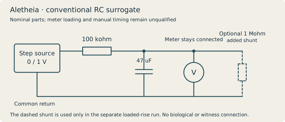
A resistor and capacitor before an amplifier
Aletheia’s acquisition work now reaches a conventional electrical surrogate. A quiet reading can still be wrong used a software target known exactly to the model. On January 22 Ibarra checks out a low-voltage source and handheld meter from the internal workshop; the team withdraws nominal 100 kohm and 47 uF parts and assembles a passive resistor-capacitor circuit.
There is no biological connection, implant, stimulation source or witness channel. On January 23 Okafor and Ibarra switch the source between nominal 0 and 1 V, leaving the meter across the capacitor throughout each run. They transcribe its display at hand-timed intervals. A separate rise run adds a nominal 1 Mohm resistor across the capacitor.
What the display did
The ordinary rise proceeds from 0.18 V at the nominal 1 s observation to 0.99 V at 30 s. The separate fall proceeds from 0.81 V to 0.00 V. With the added load, the rise reaches 0.90 V at both 20 and 30 s. A direct-source/bypass observation reads 1.00 V at the first approximately 1 s observation.
The table retains manual display transcriptions, not a fitted curve. Timing is coarse, about half a second around the intended observation; that estimate is not a calibrated uncertainty. Source accuracy, meter loading, component values and reset history have not been qualified.
Keep the equivalent circuit
Analog Devices’ RC activity provides the new source connection: response depends on the capacitor and the resistance seen by it. The earlier switched-input settling discussion is refreshed as a reason to preserve transitions and error bands, not as a description of this different circuit.
Three separate nominal calculations use ideal 100 kohm and 47 uF values. Without a load tau is 4.7 s. A modeled 10 Mohm input gives final 100/101 V and tau 470/101 s; a modeled 1 Mohm load gives 10/11 V and tau 47/11 s. Neither load value is a measured input resistance of the actual meter. The script does not generate the bench table.
A flat output is not the source voltage
The loaded run becomes quiet around 0.90 V while the direct source display is 1.00 V. That is consistent with ordinary loading of the circuit. It does not isolate every contribution or establish a time constant. Known-step repeats must record actual switching, sampling and meter loading before an unknown source is connected.
This is one conventional RC surrogate session, not a physical psychic amplifier or a completed powered witness. No participant or implant is tested. ET/ED hypotheses remain part of the research discussion; these displays do not identify such a source.
Results at a glance
| Elapsed time (s, hand timed) | Rise (V, display transcription) | Fall (V, display transcription) | Rise with added nominal 1M load (V) |
|---|---|---|---|
| 1 | 0.18 | 0.81 | 0.19 |
| 2 | 0.34 | 0.65 | 0.34 |
| 5 | 0.65 | 0.34 | 0.63 |
| 10 | 0.87 | 0.12 | 0.82 |
| 20 | 0.98 | 0.02 | 0.90 |
| 30 | 0.99 | 0.00 | 0.90 |
External research and methods
- Performance Optimization of Multichannel Data Acquisition (DAQ) Systems: The Untold Story of the Input Settling Time · Joseph Leandro Peje, Analog Devices · Analog Dialogue online article (Undated HTML edition; retrieved 2026-10-26). Input switching glitch, input settling time and first-order assumption.
- Activity: Transient Response of RC Circuit, For ADALM1000 · Analog Devices University Program · Wiki approved revision, 3 November 2021 19:14 (2021-11-03 approved wiki revision). Objective, Background and equations (1), (3), (4).